
Habersham Phase 7 Development
Habersham Land Company will provide updates every 2 weeks on Phase 7 construction activities.
Enter your email address below to be notified each time a new update is available.
Sewer Piping Almost Complete
My apologies for going 4 weeks without an update. With a dry November, things were moving very fast and we were working feverishly to stay ahead of problems. Then, Thanksgiving week hit and here we are with an update 2 weeks late.
Since the last update, J.R. Wilson completed 90% of the sewer for the project. They were able to really capitalize on dry weather and move very quickly. Most of the pictures in this update show parts of that progress. It’s not the most exciting thing to look at, but it’s better than water pipes because it at least goes up and down and through manholes! The pictures are meant to show you what is underground and what your house ties into. It may be unimportant to some and interesting to others.
As we’ve mentioned before, a lot of horizontal construction is done in layers. You start with the deepest components (typically sewer here) and then work up. Sewer, stormwater and water are all your wet utilities and they are carefully profiled by the engineer because there are not only horizontal separation requirements (i.e., water and sewer pipes have to be separated by 10’), but there are also vertical separation requirements. When you have sewer and stormwater being gravity dependent, this gets very tricky because you’re constantly changing elevation and a consistent slope must be kept. So, if you need to raise a pipe up to get the required separation over a crossing, then you’ve just changed the elevation for the entire run of pipe, which could be hundreds of feet and most likely caused an issue somewhere else. Thankfully, all of this is worked out by the engineers before construction begins.
Dry Utilities are things like power, telecommunications, street lighting, etc. Unfortunately the dry utility companies are the ones who have to design their own layout and they really don’t take wet utility depths into consideration, yet they have their own depth and separation requirements. The developer is responsible for putting in sleeves for road crossings for the dry utility companies. So, one thing that has kept us busy in the past month is figuring out these sleeve depths. There are about 40 sleeve crossings we have to put in and each one of them may have 3-5 sleeves (i.e., one or two for power, one for Brightspeed, one for Sparklight, and sometimes one for streetlight). Many of these crossings are over or under sewer pipe, storm pipe, and water pipe. The power company wants everything to be 48” deep, but then they also can’t be much more than 5’ deep because they don’t have equipment to dig much deeper. This presents a different challenge at each crossing. Each one had to be carefully worked out and then negotiated with the power company when their requirements couldn’t be met. In a few instances, we will be responsible for encasing the entire crossing in concrete due to a forced shallow depth or being too close to another utility. Because the sewer was going in so quickly, there was a lot of scrambling to get these crossings worked out before they started any storm water or water that a dry utility crossing may need to go under. You definitely don’t want to have to go back and install something underneath something else!
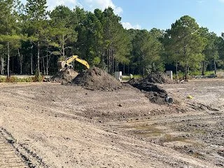
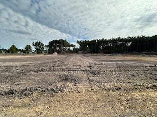
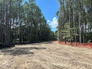
This is looking down Zeb Run, with future houses on the right where the pine trees are and a pond on the left behind the giant pile of dirt. The whole road is trenched down and the main sewer line is already in. What this is showing is where the sewer service lines come up to the house lots. Those tall green pipes will be cut off, but that is the sewer line that comes up from the main line and is stubbed up on a lot corner for a future house to connect into.
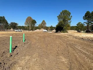
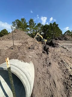
This is a view up Louis Pinckney Sr. Avenue and shows two sewer service stub ups for two adjoining lots. So, this is what is visible above ground once everything from the previous picture is buried.
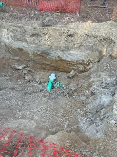
If you zoom in, you’ll see the white fitting on the end is a “Y”. This is where those stub ups shown in the previous pictures originate. This picture shows a sewer service that is coming off of a main line (that is buried). The Y is where the two service lines split off and turn upwards, one going to one lot corner, and the other to the other lot corner, just as you saw in the previous picture. Typically, sewer services come in pairs like this, with adjoining lots sharing the same lateral off the main.
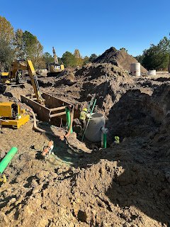
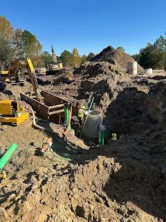
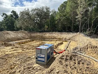
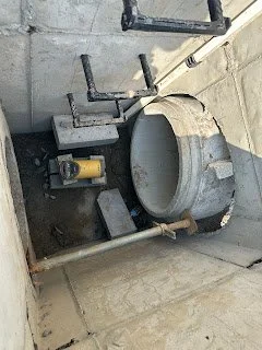
Setting a manhole section in place. The green pipe next to is not sewer pipe even though it is the same color. This is something called a “whistle,” which is a colloquial term, and you’ll see this throughout the project for the duration of the project. Similar to the well points mentioned in a previous post, these are used to remove groundwater from an area. A hose is dropped down into this pipe with some rock and connected to a pump to pump the water out.
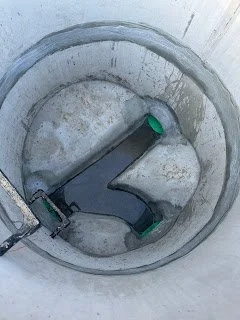
Looking down into a manhole. A manhole basically serves as access points to the pipes where they bend or tee. You can see the sewer just travels through cast channels that connect the pipes.
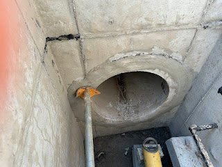
Look closely at this manhole being installed and you’ll see a pipe coming out the side of the manhole and going straight down. This is called a manhole drop and happens when a sewer line is coming into a manhole at a lot higher level than the bottom of the manhole where the deeper sewer line is exiting or passing through. As far as I know, I don’t think this is the way it was done when the earlier phases of Habersham were built. It used to be that you would just have that pipe come straight into the manhole and the sewer would just fall down into the manhole (waterfall style). The water utility company now requires these exterior drops to allow the sewer to drop to the lower level through the pipe and enter the manhole at the same level as the other connecting pipes. There are several reasons. The one that I think is somewhat comical is to prevent sewage from water falling down onto someone’s head while they may be down in the manhole working on something. Other reasons focus on minimizing turbulence. Sewage falling freely into the manhole produces more noxious gases and odors and it can also more speedily cause erosion and deterioration of the inside of the manhole.
These are two of the three live oaks that were found on the property other than the large ones up near Cherokee Farms Road. These trees actually didn’t show up on the tree survey because they were too small, but we found them in the field and realized they flanked either side of an alley entrance, so we had them saved. As you can see, the sewer goes right through the middle of them. A water line will have to go right next to one as well. The crew is doing everything they can to preserve these trees. They will undergo a good bit of stress from the large amount of disturbance in their root zone, but I hope they will make it.
This past month, we were also working on getting together all of the paperwork needed to legally record the platted lots. Once lots are recorded, you are legally allowed to sell a parcel as long as you bond 125% of the infrastructure cost (to prevent a developer from selling a lot and skipping town before roads or utilities are put in for that lot!). We got our plat recorded so that we could close on the parcels that Habersham Row is purchasing. They just received their water and sewer permits for their project and will hopefully be able to get all of their other needed permits in time to start construction in a few months.
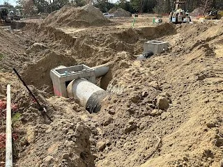
Stormwater pipes being joined into a box before being mortared in. The black fabric you see wrapped around the pipe goes around each pipe joint to help prevent dirt from getting into the cracks and causing a sinkhole.
So, what’s coming up? Stormwater pipes and boxes will be ongoing and some of the water lines will start going in in certain areas. Stormwater pipes will be the big concrete pipes and the water pipes are the bright blue pipes. Below is the map showing everything that is in the ground so far.
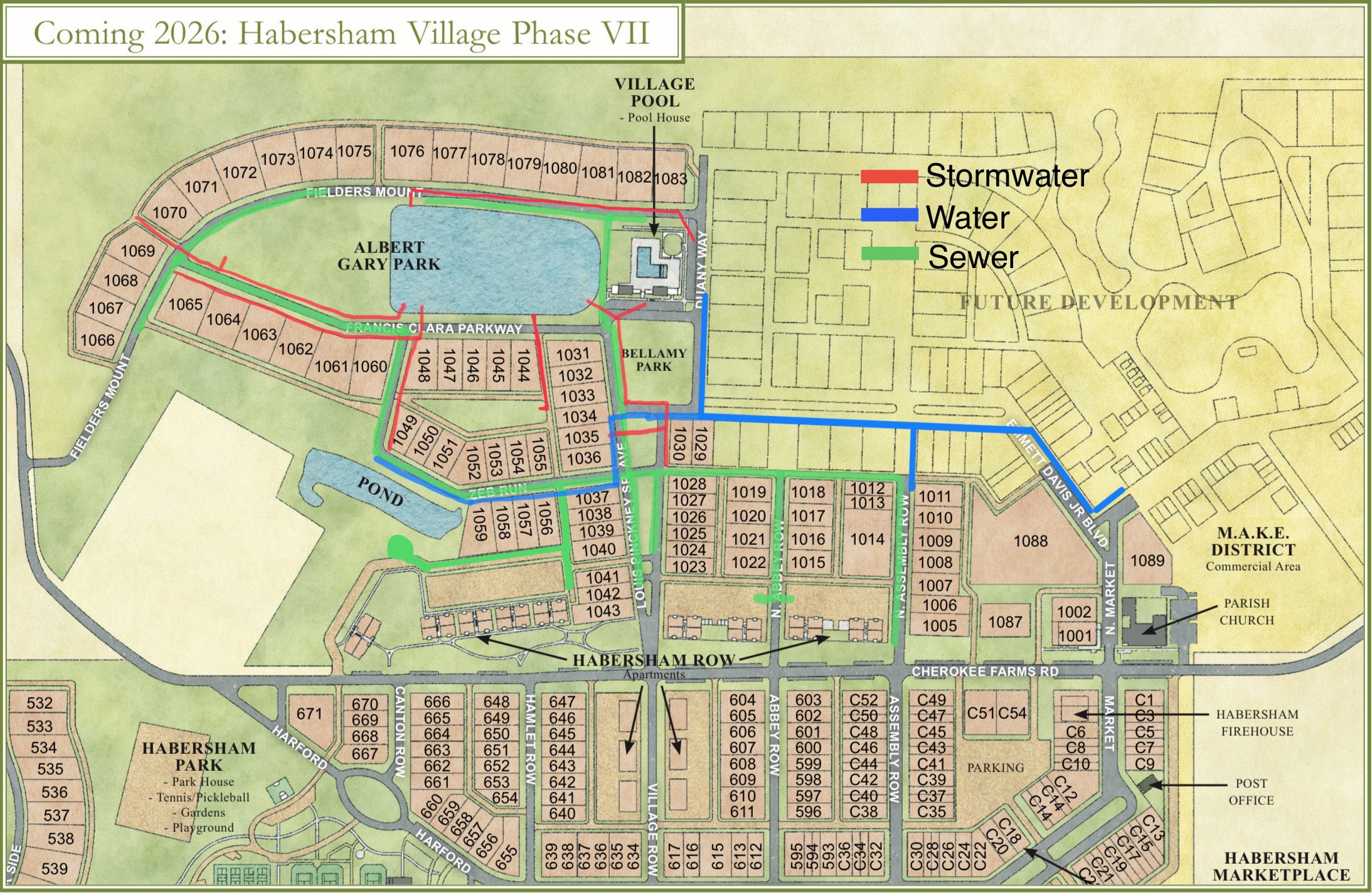
Map showing what has been put in the ground so far. Approximately 30%-40% complete.
Wet Well Installation (emphasis on the “wet”!)
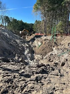
In a previous post, there was an introduction to what a pump station is and the preparation for the wet well installation for that pump station. It is the receiver of all of the project’s gravity sewer, which means it is the deepest part of the sewer system. The earlier post showed the well point system that was set up to prepare for this deep hole that must be dug. This post will show the installation of the wet well and the challenges that came with it.
Digging a hole that goes below sea level can be challenging enough. Unfortunately, there were some other factors that added to the difficulty for this particular job. One factor was the weather. We just had not had a lot of sunshine to help dry things out and had more wet weather on the way with 2 hurricanes looming off the coast. In addition, the location of the wet well is on the edge of the “limits of disturbance”. Part of the construction permit that is required by one of the state agencies is that you have to establish limits of disturbance, which a lot of times is where the silt fence is located. The earth cannot be disturbed beyond that line. In this case, the limit of disturbance was determined by the required 100’ buffer in this area, so it was as far as it could be anyways. What made it difficult is that it was close enough to the wet well location that it did not allow for the proper benching on that side of the hole. Instead, it was more like a shear wall of dirt, which can be dangerous because of caving in, but also makes the digging very difficult because of constantly having to deal with the dirt sliding down into the hole.
We set up a Timelapse video of the process of setting the wet well to help show the process from beginning to end. In the Timelapse, you can see the difficulty the contractor encountered throughout the week. Things had to be done multiple times dues to the wetness and the walls sliding in. It was a rough week for the contractor, but in the end, they got it set correctly and were able to start backfilling. The time lapse below had to be broken into 2 videos due to limits on file size, but know the second is a continuation of the first.
In the video, you’ll see them first digging down as far as they can and then setting the trench box to allow them to prepare the base where the bottom of the wet well will sit and to provide a safe place to work. You’ll then see the crane lifting and setting the different pieces of the wet well. They then had a hard time getting their trench box out due to more rain and dirt sliding in from around the wet well. The video ends prior to the full trench box coming out and the remaining sections placed on top, but we have pictures showing everything in place.
After letting it sit a week and getting some good sunshine, the top piece was set and it was properly backfilled and compacted. The contractor then began running the sewer line out from the wet well to the first manhole, which is almost just as deep as the wet well. The sewer line is continued out from manhole to manhole, going from the deepest point outward. So far, this week, the contractor has gotten in approximately 4 manholes and about 400’ of sewer pipe out from the wet well location. Rock is put around the entire length of the sewer pipe to help prevent the pipe from settling. A trench box is continued to be used with this deep sewer and can just be dragged as they dig the trench and lay the pipe.
Coming up this week, multiple crews will be on site and they will continue to lay sewer. In addition, while the contractor was waiting for things to dry out a little after setting the wet well, some water pipe was laid. Water is typically done after sewer because it is only 4’ deep and therefore goes on top of everything. Thankfully, there is a pretty decent length of water pipe that doesn’t have anything underneath it, so they were able to go ahead and knock this section out last week while things were wet.
The Master Plan
"Ideas never die, Sire, and, though they may slumber for a time, they wake up stronger than when they fell asleep" -The Count of Monte Cristo by Alexandre Dumas
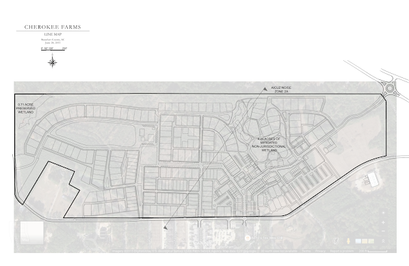
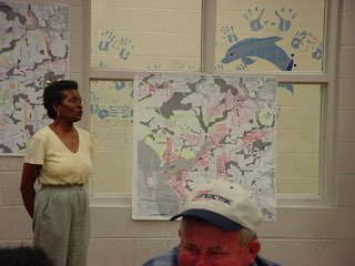
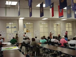
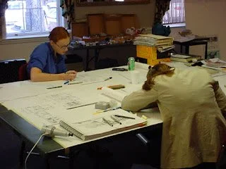
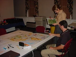
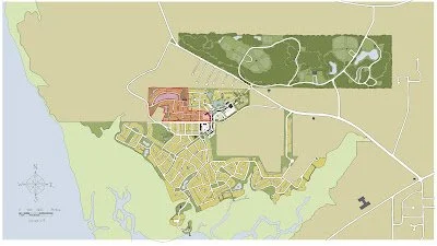
The master plan for the tract that encompasses Phase 7 was originally designed in 2002 for the previous land owner, Tim Rentz. Ironically, it was my first design charrette, as I was 19 years old and interning with Duany Plater-Zyberk & Co. (DPZ) while studying Landscape Architecture at Clemson. The project was called Cherokee Farms. Bob Turner had convinced the land owner to use the same town designer as Habersham so that the two developments could compliment each other. Two other future Habersham residents were also part of the DPZ design team, Mallory Baches and Demetri Baches. In addition to the master plan for Cherokee Farms, we also completed a regional study for the county to show where it made sense to encourage pedestrian oriented development with neighborhood and town centers, along with a regional network of 2 lane interconnecting roads and regional greenways.
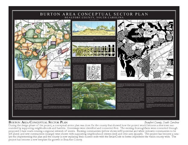
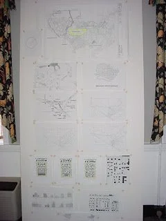
Regional Plan done for the Burton area during the Cherokee Farms Design Charrette in 2002. Orange areas depicted pedestrian shed (5 minute walk from edge to center) potential locations, purple was civic, red commercial, yellow were existing more rural neighborhoods, and green was open space.
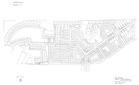
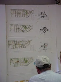
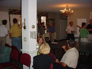
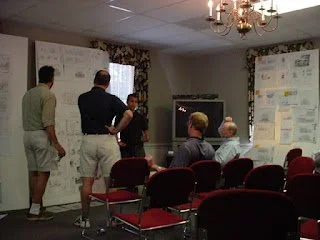
The design charrette for Cherokee Farms took place at the Sea Island Inn on Bay Street and was an intense 10 day collaboration that involved town designers, architects, civil engineers, traffic engineers, builders, county officials, politicians, fire chiefs, surrounding residents and more. All of the key stakeholders were part of the process in creating a master plan that they all could support. Tom Low, with DPZ, led the charrette and is the same town planner who led the Habersham charrette 5 years earlier. The master plan that came out of the charrette is below. It included a mix of housing types, ground floor retail, civic sites for future churches, libraries, schools, etc., plenty of green space and a neighborhood pool.
Original master plan from the Cherokee Farms design charrette in 2002.
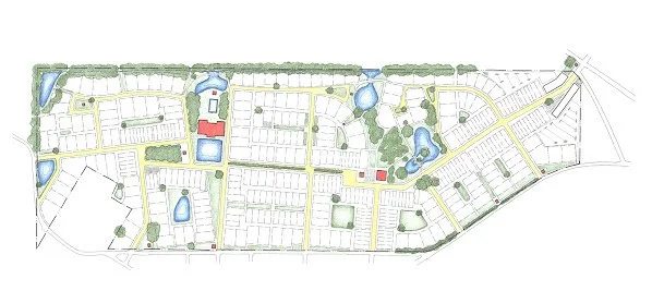
A few years later, the land owner formed a joint venture with Habersham Land Company to develop the project under the Habersham PUD zoning so that it could have the same design standards as Habersham and be an extension of the Habersham neighborhood rather than a separate development. As the design went through the early permitting process to be rezoned, the master plan was tweaked to accommodate new stormwater requirements, AICUZ restrictions, wetlands mitigation and other things. That master plan is below.
Revised Master Plan in 2006 to meet permitting requirements
Then, after the Great Recession in 2008, the landowner needed to sell the property so Habersham Land Company purchased it under a land holding company to protect it from outside development that may not be compatible with Habersham. HLC continued the efforts in rezoning and continued to meet roadblocks. We then helped the county write a new zoning ordinance for Traditional Neighborhood Development, which then allowed the project to move forward with its current zoning rather than be rezoned into the Habersham PUD. Since then, the County has adopted a Form Based Code, which is even better and permits developments like Habersham. Still, things like stormwater, buffers, and AICUZ requirements continued to change, so the master plan would be tweaked again into what it is today and locked in with a development agreement.
Even though changing requirements required tweaks, the bones and intent of the original master plan were held onto as much as possible. There were good ideas that came out of that 10 day charrette and those ideas were put on paper and there was buy in from all the stakeholders. Good ideas are worth holding onto, even if it takes 23 years to see them come to fruition.
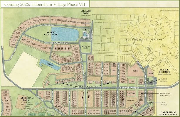
The above image shows the plan for the current phase of development. You’ll see some of the features that have been mentioned in previous blog posts, and now having the plan graphic available, we’ll be able to refer to more things going on with construction as it relates to the plan. Looking at the different master plan versions over the years, you’ll see the long, carrot-shaped green along Cherokee Farms Road is part of this phase and is still oriented around the large live oak tree that is at the end of Hamlet Row. A green finger, in the form of an Avenue, extends across from Village Row and ends at the pool on a neighborhood square. An Avenue is a thoroughfare that connects two urban centers and typically has a landscaped median and terminated axes. This Avenue is named after Louis Pinckney Sr., who was one of the last living members of the family who last lived on the Habersham property and was able to share so many stories of the land with Bob when he first started Habersham.
The pool also looks out over the pond and park to the west as it has since one of the early master plans that was done. This entire block, consisting of the pool, pond and green space is called Albert Gary Park. As many know, Albert is more commonly known as “Lug” and this park is a way to honor him as a person and his contributions to Habersham for so many years. The street that borders the park to the south is named in memory of Lug’s parents, Clara and Francis Gary, whom Lug described as inseparable and thus, their names will be shared on a street sign and their street will hug the park bearing their son’s name.
Connecting the neighborhood square to the east side is a future boulevard, as in the original master plan, that will only be stubbed out in this current phase. That boulevard will connect to the future town square, just north of the Parish Church. The name of that Boulevard is Emmett Davis Jr. Blvd. Mr. Davis was one of the founders of the engineering firm Davis & Floyd and the father of Stephen Davis, Bob’s partner in developing Habersham. Mr. Davis was instrumental in helping Bob and Stephen get Habersham started in the early days.
The overall block pattern in the site plan reflects the original master plan other than some of the street connections to Cherokee Farms Road because of needed adjustments to meet the County’s access management requirements. So, even though it has been 23 years since the design charrette was done for this piece of land that was originally going to be a separate development, the good ideas that rose to the top during that process have stood the test of time and will be implemented to help strengthen the existing interconnectedness of Habersham and continue the harmonious evolution of a neighborhood.
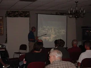
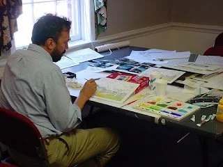
More about the plan will be discussed in future posts. Below are some pictures from the original design charrette in 2002.

Setting Well Points and Other Prep
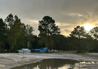
The last two weeks have been mostly about preparation. There has been a little bit more of the pond dug. Most of the dirt moving involved filling is some of the former agricultural ditches and rerouting others to help take care of the site runoff during construction. Primarily, though, the contractor has been busy accepting deliveries of materials and moving those materials to appropriate storage areas. Lots of concrete stormwater pipe and stormwater boxes are now on site, as well as much of the sewer and water pipe. Sewer pipe is green and water pipe is blue. These colors are standard for these utilities. When you see utilities marked in Habersham prior to some work being done, you’ll often see green and blue spray paint on the ground. Green is marking where there is a sewer pipe underground and blue a water pipe.
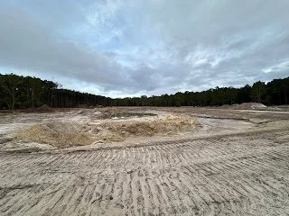
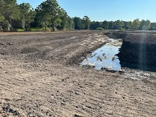
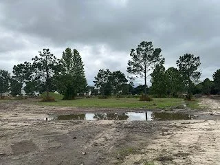
What the pond looks like this week
Stormwater boxes of all different sizes lined up, waiting to be put in the ground.
Water pipes stacked up in the distance along with other materials for water and sewer installation
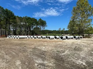
Concrete stormwater pipes
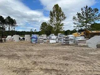
Various materials recently unloaded from a truck
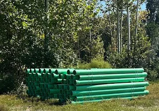
First delivery of green sewer pipes on site.
These types of material deliveries are very time consuming. They require big equipment to unload the trucks because of the size and weight of each object. Then, each item has to be carried individually to where it will be stored. Organization is important as the size and weight of these materials make it not easy to just move around if they end up being in the way.
The most interesting work that took place a couple of days is setting well points for the preparation of digging the deep hole for the wet well, which was described in the previous blog post. Well points can be thought of as vertical French drains that use a pump to bring water up. A 2” pipe that is 30’ long is inserted straight up and down into the ground. At the bottom of the pipe, the end is capped and there are small slits in the bottom 2’ of the pipe. The top of the pipe is above ground and connected to a larger pipe that is connected to a pump. The pump creates a vacuum in the pipe which draws groundwater in through the slits and sucked up into the larger pipe, which passes through the pump and is pumped out to the neighboring pond. Many of these are placed every few feet around the perimeter of the hole you need to dig and all connected. The goal is for these pipes to suck the ground water out of the area you will be digging so that you are not battling water when you dig beyond the water table. We’ll find out if it worked when the wet well is dug!
The video below shows how this work is done. What you’re seeing in this video is an excavator with a special ram rod hung from its bucket. The ram rod has water pumped through it and is constantly shooting water out of the end. As the excavator rams the rod down into the ground, the water jet is displacing the soil. The video starts with the ram rod being pulled out and then immediately moving to the next location. As the rod is pulled out, the crew quickly pushes one of the yellow pipes down into the hole. You can see how far down these pipes go. Some rock or sand is dumped in afterwards to help keep the slots from getting clogged with dirt. This process is repeated to border the future hole on 3 out of 4 sides with well points every couple of feet.
The picture below shows the finished product. You can see the tops of all the yellow pipes are connected to the larger perimeter pipe laying on the ground, which is connected to the pump. Each of those yellow pipes has water being pulled up from 20’ down and that water is being pumped into the pond next to it. Hopefully this will make it easier to dig in a few days.
Once the well points were set, the crew began putting together something called a trench box. This trench box, shown below will be lowered down into the bottom of the hole once it is dug and create a safe place for people to be down in the hole working to set the wet well. Everything is prepared and the next blog post will hopefully show the wet well being dug!
First Pipe in the Ground!
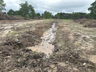
There has been a lot of activity in Phase 7 the past two weeks! The pond continues to be dug, first stormwater pipe is being installed, the sewer wet well digging has begun, and lot corners are being staked by surveyors. You may start to see some signs of street locations as well. With all of the digging, the dirt has to go somewhere, so much of it is distributed around the site in places where it can begin to dry out and potentially be used as the project moves forward for base material. Some of where it is being spread is where roads will eventually be cut in. It is also being used to begin filling in the old farm ditches that criss cross the site.
Dirt from the pond being spread where a road will eventually be cut in.
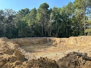
You can see the pond is gradually getting bigger. It looks like the engineers did a good job in their design as the depth is right at where groundwater is just beginning to come in.
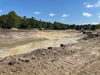
The pond has gotten much larger with the whole north bank almost cut in. The bottom of the pond is right at the water table, which is why there is a little bit of water at the bottom.
Storm drain boxes and pipe started to get delivered. You may remember a previous post that showed the careful attention to the design of each one of those boxes. Now, you can see what those look like. They’ll each have concrete tops placed on top that will hold the iron grates, which will eventually be all you will see from above ground. As you can probably guess, the large holes are where the concrete pipes get inserted and mortared into place. The smaller holes towards the top are for French drain pipes extending out from the boxes to help keep the ground dry around road bases.
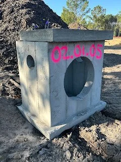
Storm Drain Box with large hole for concrete storm pipe and small hole for French drain. Concrete lid sitting on top.
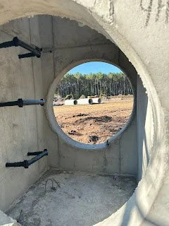
Looking through one of the storm drain boxes.
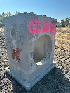
Another example of one of the storm drain boxes that will be put in. Each one will have an iron grate on top, which is what you would see above ground.
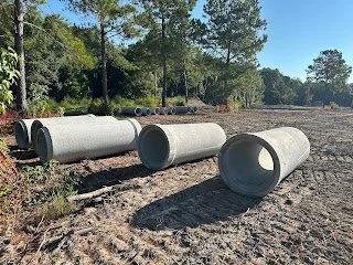
Some of the concrete pipes that will be used to transport stormwater runoff to the ponds.
An example of a pipe that has been inserted into a box but not mortared yet. Each pipe has to be set at an exact slope so that it will connect into the next box at the right height (and because water runs downhill!)
Here’s the other side of that box where the pipe has been mortared in.
Typically, most pipe laying will start with the deepest and work its way back. So, much of the first storm drain pipes that will be going in first will be the ones that empty into the ponds. These are the outlet pipes. They will work back from there in most cases. You can see the first outlet that was put in last week.
This shows the outlet pipe exiting into the pond. Once the pond is full, the pipe will be underwater. The contractor starts with the outlet pipe and works their way backwards from there when laying the pipe.
Outlet pipe looking back to where the contractor is digging to set the first box.
The sewer pump station site was staked out and the digging has begun for the wet well. If you are unfamiliar with pump stations, you can find 4 pump stations in Habersham. One is behind a fence on your left just before you get to the car gate going to the pool. Does anyone know where the other 3 are? If so, put your answer in the comments. For those unfamiliar with pump stations, here is a short video found on YouTube that gives a simple explanation of what they are and how they work:
Basically, gravity is used to get all sewer to this point. It all drains into the pump station’s wet well, which is essentially a tank. Because it is fed by gravity and we get no help from topography in the Lowcountry, it has to be pretty deep! This particular one will be 27’ deep!! Digging a hole with a bottom that is 7’ below sea level presents challenges and we can show that process in a future post. For now, the contractor has dug a hole down to the water table, which is 8’-10’ deep. The schedule for digging the rest and setting the wet well in (with a crane) will depend on the weather and how much water they run into down deeper. By the way, the existing pond next to this location was drained dry to help with this. Because of it’s proximity, digging a deep hole will cause the water in the pond to travel laterally underground to the deeper hole because the groundwater will be sucked into the hole, causing the pond water to infiltrate into the soil more and then into the hole itself. Draining the pond helps minimize the amount of water that has to be dealt with while digging. More to come on that!
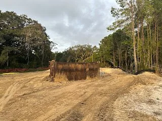
Pump Station location. The hole has been prepped and the first 10’ dug out. Although the Wet Well will only be 5’-6’ wide, the hole starts out 40’x40’ because of how deep it will end up having to be.
Digging Begins
Since the last post, we’ve had a couple of sets of back to back days with no rain, which has really helped dry things out. The crews have ground up all of the stumps and have begun moving dirt. The work is starting with digging the pond. This will allow the opportunity to use the pond to deal with stormwater during the construction phase and will also provide fill dirt for building the roads up. You can see this already starting to happen with the roads being put in around the pond.
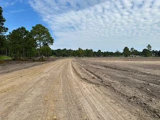
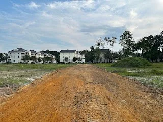
This is the beginnings of a road, with lots on the left overlooking the pond on the right.
Here in the lowcountry, most of the time your pond depth is determined by the water table. Geotechnical work was done prior to engineering design by drilling down in several areas on the property to determine the water table depth. Then, the engineers used this information to design the pond. That depth then drives the size of the pond needed to accommodate the volume required by the local ordinances. In Beaufort, new developments are required to maintain 1’ of freeboard (“extra space”) for a 100-year storm event, and you have to be able to hold it for a certain length of time before water leaves the site. That requires a lot of storage room! Instead of digging a big hole that only has a small amount of water in it most of the time in order to maintain volume for 100-year storms, we have designed a dry pond to accommodate the storage requirements. A dry pond is a lower area that temporarily fills up with water when the wet pond’s capacity is reached. The way we have designed it is to be a large park that is sodded, so that it can be used while it is dry. We have attached a picture of a similar concept at Alys Beach in Florida. Habersham’s will not be as urban as this one is, but you can see how a park can be made out of something that is also functional for stormwater.
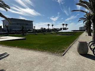
Dry Pond at Alys Beach in Florida that doubles as a sunken urban park with amphitheater stage.
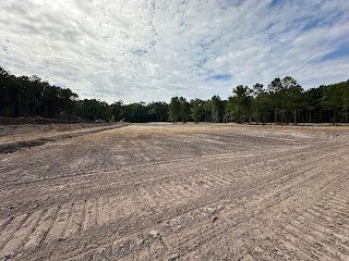
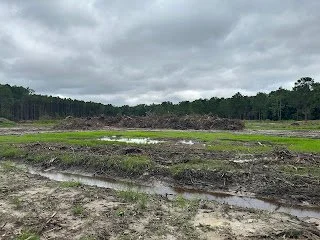
Hard to see, but the beginnings of the dry pond sunken area, taken from the dike separating the wet pond from the dry pond.
Looking ahead, the contractor will continue moving dirt around and there should be some materials starting to be delivered to the site in the next few weeks. In addition, the surveyors will be out in another week to start staking all of the lot corners. This may seem wasteful as almost all of them will be destroyed, but it is unfortunately required in order to record the plat. And the plat must be recorded to transfer property, which we will need to do for the model homes and multi-family to be able to start prior to the infrastructure being completed. More on all of that in a future post. But prior to the next post, you may see a bunch of stakes being put in the ground and that is what they will be doing.
Here are some more photos of the progress...
Looking down the dike separating the wet pond on the right from the dry pond on the left.
Reached the water table!
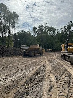
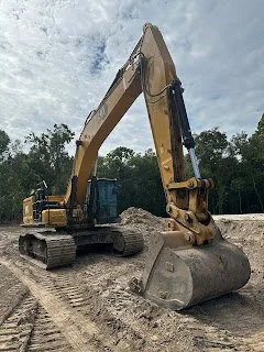
The machines doing the heavy lifting
Wet, wet, wet….
It has been a very wet last two weeks. It hasn’t slowed things down too much since the work has consisted mainly of pulling and piling stumps. We do hope it dries out some before topsoil starts to be removed and grading begins. This phase is fortunate to have all of the old farm ditches criss-crossing the property as these really help keep things drained and help pull some of the saturated groundwater out.
Earlier this week, the wood chippers arrived on site and they have begun chipping the stumps. It will probably take them a week or so to get everything chipped and hauled off. Having done so, the site will be pretty well cleaned up and ready for preliminary grading.
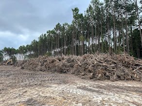
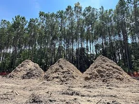
Stumps piled up prior to chipping and stumps after being chipped into mulch
Offsite, we are working with the engineers and contractor to review and approve every one of the concrete structures that have to go in the ground. This includes all the stormwater boxes (the things underneath the metal grates you see on the edge of roads) as well as sewer manholes. There are over 70 stormwater boxes and every single one of them has to be designed to exact dimensions based on the elevation it is set at, the size pipes that are coming and going from it, and the exact elevation down to the hundredth decimal of the bottom of each pipe. An example is shown below. At the same time, we are working with Beaufort Jasper Water and Sewer Authority to get their approval on every piece of material that will be part of the water and sewer system (i.e., pipes, valves, hydrants, manhole covers, couplings, meter boxes, etc.). They review and approve the specs and manufacturer of each piece. This is because they will take ownership of the whole system after it is put in. It’s a $4 million gift to them ;-)
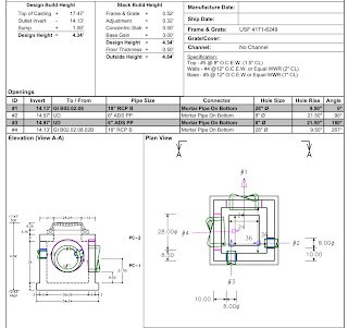
An example of a stormwater box design to be custom made out of concrete.
Once everyone is ok with everything, materials can be ordered and we’ll start seeing things show up on the site.
Here are some pictures with explanations from the past two weeks.
Future alley is cleaned up from all stumps and ready for grading
Future pool will be right where the large puddle of water is with a large pond and park beyond.
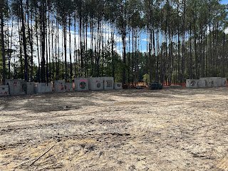
Trees preserved in a future neighborhood park
Once we have the master plan rendered to share, we’ll start showing where photos are taken on the plan. More to come neighbors...
Work Begins…
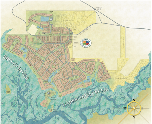
Phase 7 Highlighted on 2009 Conceptual Master Plan (for visual study only) to show context
We received our development permit for Phase 7 from Beaufort County on July 9 after 3 years of permitting. Much of the time was waiting on required state permits, which are more rigorous since we are in a coastal area. Stormwater permitting is also very time consuming, as Beaufort County has some of the most stringent stormwater requirements in the country. Phase 7’s stormwater report is over 500 pages long! But, alas, all permits were received and work began on July 12 after a successful pre-construction meeting on July 11 that also involved our first inspection. This first inspection is to make sure all of your silt fencing and tree protection is correct and you have proper construction entrances in place, and proper documents on site.
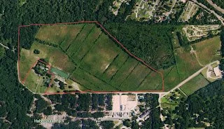
The first phase of construction is everyone’s least favorite. Clearing trees. It is always hard to see trees come down. Especially if you’ve only known the site as a tree filled property. But, some of our older Habersham residents may remember when this property was farmed for cucumbers not that long ago. Here is an aerial from just 20 years ago and you’ll see the only trees in this phase of development were in ditches!
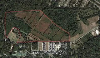
Then, here is an aerial from just over 10 years ago. A pine forest had grown up on the western side, but the fields still mainly were kept cut.
Then, below is an aerial from last year and you can see how much growth can occur in just 10 years.
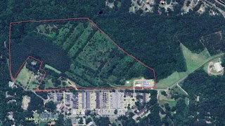
A lot of those trees that grew up in the fields are being saved and will either be on lots or in open spaces. Much of the pine forest will be maintained as an 100’ buffer on those edges of the property. Unfortunately, the trees in the ditches (all the straight lines in the aerials) cannot be saved. Ditches have to be filled in and the trees down in the ditches cannot survive with that fill on top of them. Some of those ditches are over 5’ deep! So, many of the trees that we see coming out are those trees that have grown up in the numerous farm ditches that criss-cross the property.
The contractor had a timber company come in to do the cutting and there is a good chance most of the trees will become pulp wood. Although it is hard to see trees come down, we have to admit that this machine is pretty impressive! Yikes!
About 93% of the caliper inches that were removed were non-specimen trees. Specimen trees that were removed will be mitigated inch for inch with new tree plants and non-specimen trees that were preserved. The county does not count preserved specimen trees towards mitigation, but there are some great specimen trees that are part of the trees being saved.
It took about a week and a half to remove the trees and now they are in the process of hauling them out. Behind them come the stump snatchers. You can’t leave those stumps in the ground! Every single one has to come out and that process will take much longer than the trees. We expect them to spend about 4 weeks removing stumps and finish grubbing the site.
More to come neighbors….